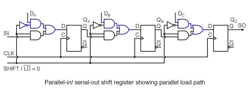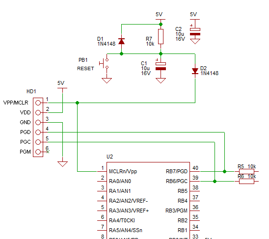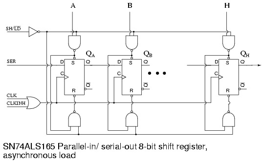
- #CIRCUIT DIAGRAM OF PARALLEL TO SERIAL CONVERTER SERIAL#
- #CIRCUIT DIAGRAM OF PARALLEL TO SERIAL CONVERTER PC#
#CIRCUIT DIAGRAM OF PARALLEL TO SERIAL CONVERTER SERIAL#
The TxD line, pin 3, CTS line, pin 8 and the DSR line, pin 6, of the serial port are used - see diagram. It converts a serial 2400 baud signal into a parallel signal.

After Q1 phase inversion, the re and De of MAX485 are in high level and in data sending state.This converter may help if just the serial port on a personal computer is free, whereas the printer needs a parallel (Centronics) port.
#CIRCUIT DIAGRAM OF PARALLEL TO SERIAL CONVERTER PC#
When the PC sends data, the 9-pin output of nih232 is in low level. After Q1 phase inversion, the re and De of MAX485 are at low level and in data receiving state. At ordinary times, the 9-pin output of nih232 is at high level. Since both DTR and RTs are used for power supply, TX line, another channel of hin232 and Q1 are used to control the state switching of MAX485. In the use of half duplex, the two pins can be connected directly, and then the high and low level output by PC or MCU can make MAX485 switch between receiving and sending states. When re is low, MAX485 data input is valid When De is high level, MAX485 data output is valid. MAX485 controls data input and output through two pins re (2 pins) and de (3 pins). Therefore, the function of D3 in the circuit is voltage stabilizing rather than voltage limiting. After actual test, the VCC voltage is about 4.7V.

After D3 voltage stabilization, the VCC is obtained. When using this circuit, it should be noted that the PC program must make the DTR and RTs of the serial port output high level. The experiment shows that the circuit can work normally with only one of the wires. Each wire of PC serial port can provide about 9ma current, so the current provided by the two wires is enough to supply the circuit. For the convenience of use, the power supply part is designed as passive mode, and the power supply of the whole circuit is directly stolen from the DTR (4-pin) and RTS (7-pin) in the RS232 interface of PC. The 232 level conversion circuit of this circuit adopts nih232 or MAX232 IC directly, and the 485 circuit adopts MAX485 IC. Rs232-485 converter mainly includes power supply, 232 level conversion and 485 circuit. On this basis, users can establish their own high-level communication protocols. RS-232, RS-422 and RS-485 standards only specify the electrical characteristics of the interface, and do not involve connectors, cables or protocols. Because the standard proposed by EIA is prefixed with RS, it is still used to prefix RS in the field of communication industry. Meanwhile, the driving capability and conflict protection characteristics of transmitters are added, and the common mode range of bus is expanded, which is later named TIA / eia-485-a standard. In order to expand the scope of application, EIA developed RS-485 standard based on RS-422 in 1983, which added multi-point and two-way communication capability, that is, multiple transmitters are allowed to connect to the same bus. RS-422 is a one-way, balanced transmission specification with single transmitter and multi receiver, which is named TIA / eia-422-a standard. In order to improve the short distance and low speed of RS-232 communication, RS-422 defines a balanced communication interface, which increases the transmission rate to 10MB / s, extends the transmission distance to 1200m (when the rate is lower than 100kb / s), and allows up to 10 receivers to be connected on a balanced bus. It is proposed to make up for the deficiency of RS-232. Therefore, RS232 is only suitable for local communication. The RS-232 is designed for point-to-point communication. The maximum transmission distance is about 15 meters and the maximum speed is 20 KB / s. RS-232 was released in 1962, named eia-232-e, as an industrial standard to ensure the compatibility of products from different manufacturers.


RS-232, RS-422 and RS-485 are serial data interface standards, which were initially formulated and released by the Electronic Industry Association (EIA). Brief introduction of RS-232, RS-422 and RS-485


 0 kommentar(er)
